The Electronic Control Unit (ECU) is the brain of any modern vehicle. It monitors and manages crucial systems such as fuel injection, ignition timing, air–fuel ratio, emissions, and even advanced driver assistance features. When the ECU develops faults, the entire performance of the vehicle can be compromised. That’s why being able to diagnose ECU problems accurately is a skill every automotive technician and engineer should master.
In this guide, you will learn a step-by-step process to diagnose an ECU in just eight practical stages. This method, widely used by professionals in automotive electronics, will help you perform a quick and reliable preliminary analysis of ECU-related faults. Whether you are a beginner in automotive repair or a seasoned professional, these steps will save you time, effort, and money when troubleshooting electronic control units.
Step 1: Create a Technical Sheet for the Vehicle
Before diving into the ECU itself, start by gathering all the necessary information about the vehicle. This technical sheet will serve as your roadmap and help you determine whether the problem is truly ECU-related or if it originates from another system.
Key questions to include in the datasheet:
- What is the make, model, year, and engine type of the vehicle?
- What type of fuel does it use (gasoline, diesel, LPG, hybrid)?
- How and when did the problem start? Did it appear after a repair or maintenance service?
- Were any diagnostic tests already performed?
- What is the fuel pump pressure and is the pump operating correctly?
- Does the scanner establish communication with the ECU? If yes, what error codes are displayed?
- Are the spark plugs firing properly?
- Are the injectors functioning?
- Is the Check Engine Light (MIL) on?
- What is the status of the immobilizer light (steady, flashing, off)?
- Has the vehicle undergone modifications (e.g., gasoline-to-LPG conversion, gearbox swap)?
- Is the electronic throttle body operating as expected?
- Do sensors receive proper voltage and ground supply?
By answering these questions, you can form a clear picture of the issue. Many times, technicians misdiagnose problems as ECU-related when the root cause lies elsewhere in the vehicle.
Step 2: Identify the ECU Model
Once you have the preliminary data, the next step is to identify the exact ECU model. This can be done in two ways:
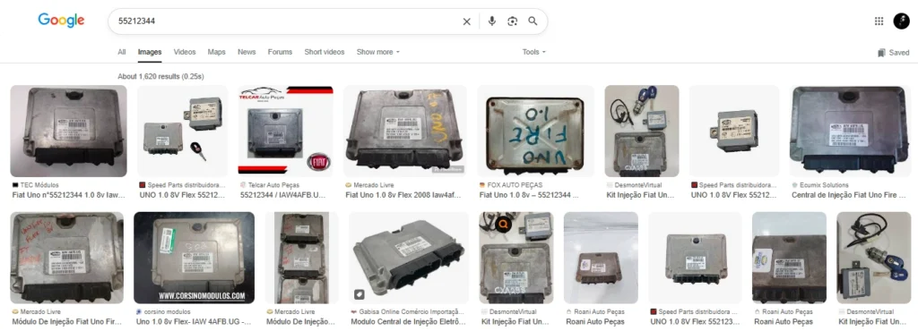
- Check the ECU nameplate or label. Most ECUs come with printed details such as manufacturer, model number, and part number.
- Use a diagnostic scanner. If the nameplate is missing or unreadable, connect your scanner to retrieve the ECU number. You can then search this number online to get the complete specifications of the module.
Knowing the ECU model is crucial because wiring diagrams, pinouts, and troubleshooting methods vary between manufacturers such as Bosch, Siemens, Delphi, and Magneti Marelli.
Step 3: Obtain the Electrical Diagram
Having the wiring diagram of the ECU is essential. Without it, you will be “flying blind.” The diagram shows the pin configuration, including power supply pins, ground connections, communication lines (CAN, K-Line), and sensor/actuator inputs and outputs.
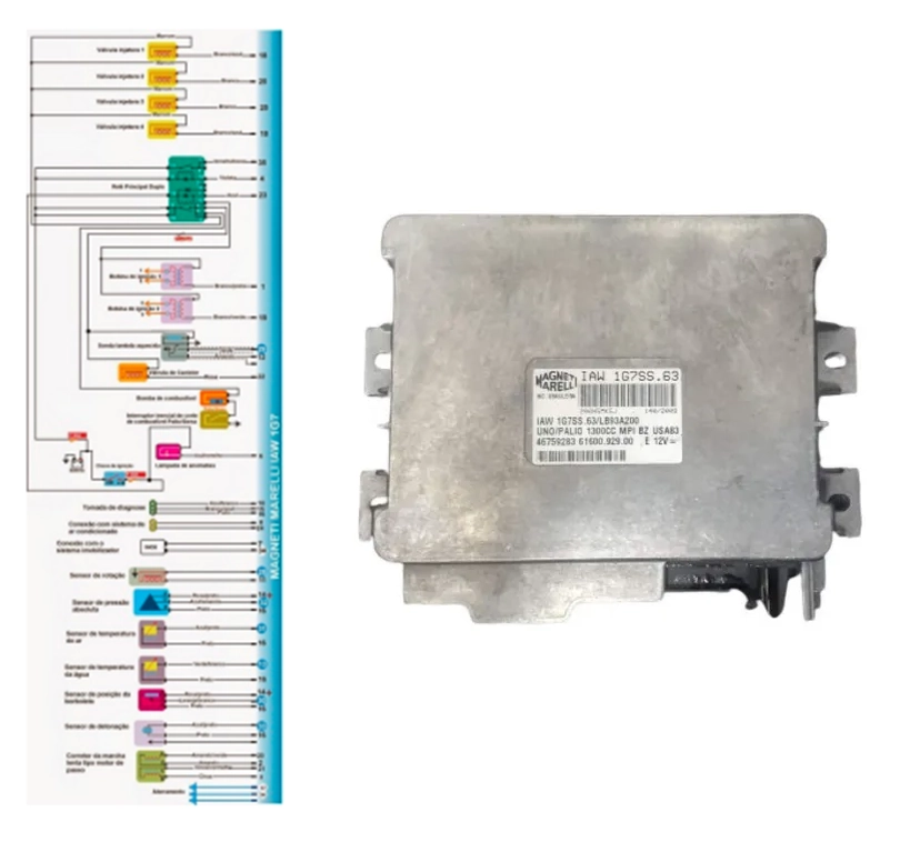
FFor example, in a Fiat Palio 1G7 ECU, pins 17 and 34 serve as ground, while pin 35 is the positive power supply. This simple reference ensures you know exactly where to test voltages.
Step 4: Check Power and Ground Continuity
Power supply and grounding issues are some of the most common causes of ECU malfunction. To test them:
- Set your multimeter to continuity mode.
- Place the black probe on the chassis ground and the red probe on the ECU’s ground pins (e.g., pins 17 and 34 in the Fiat example).
- Repeat the same with the positive pin (e.g., pin 35).
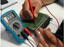
Look for loose, broken, or corroded solder joints on the ECU connector or PCB (printed circuit board). Even minor cracks can interrupt the flow of current and cause intermittent ECU failures.
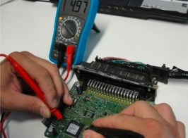
Step 5: Measure Supply Voltages
After confirming continuity, the next step is to check whether the ECU is actually receiving proper supply voltage.
- Connect the ECU to a regulated power supply or the vehicle’s battery.
- Measure the voltage between the positive pin (e.g., pin 35) and ground (pin 17).
- You should obtain a stable 12 volts.
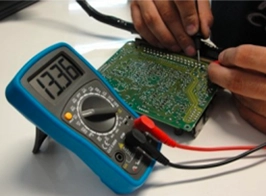
Check that this 12V is correctly distributed along the ECU board and adjacent tracks. Missing supply in certain areas may indicate a burnt track or damaged connection.
Step 6: Test the Voltage Regulator
Every ECU contains a voltage regulator that converts the 12V input to a stable 5V output. This 5V is used to power the microcontroller, sensors, and memory chips.
To test it:
- Set your multimeter to 20V DC.
- Place the black probe on ground and the red probe on the regulator’s input terminal. It should read 12V.
- Move the red probe to the output terminal. A healthy regulator will output 5V.
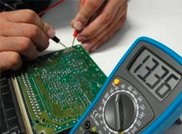
If the regulator is faulty, the ECU will fail to operate or display erratic behavior. This is a very common ECU issue that can often be resolved by replacing the regulator component.
Step 7: Measure the Injection Driver Voltage
The injection driver is responsible for controlling the fuel injectors. Even though measuring its voltage is not a conclusive test of its functionality, it helps determine whether the driver IC is receiving proper supply.
- Place your multimeter on the IC’s supply pin.
- You should measure around 5V.
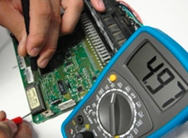
If there’s no voltage, the driver circuit might be faulty or disconnected.
Step 8: Measure Processor and Memory Voltages
Finally, check the microprocessor and memory chips inside the ECU. These are the components that store and execute the vehicle’s software.
- Their supply voltage should also read 5V.
- Additionally, you can check the oscillator crystal (the clock generator for the microprocessor). It should measure between 1.8V and 3.3V, depending on the ECU brand and model.
If both the supply and oscillator voltages are correct, the processor is most likely running. If not, the ECU may need advanced repair or replacement.
Extra Tips for Professional ECU Diagnosis
While the above steps provide a reliable preliminary diagnosis, advanced troubleshooting often requires professional equipment and deeper expertise:
- Oscilloscope: Used to analyze communication signals, waveform patterns, and detect irregularities in real-time.
- Test Bench (ECU Bench Setup): Allows you to test the ECU outside the vehicle by simulating inputs and outputs.
- EEPROM Programmers: Useful for reprogramming memory chips or cloning ECUs.
- Thermal Camera: Can help detect overheating components or short circuits inside the ECU.
With these tools, technicians can move beyond basic tests and accurately repair or reprogram faulty modules.
Conclusion
Diagnosing an automotive ECU may sound complex, but by following this 8-step process, you can quickly determine whether the ECU is faulty and identify the root causes of its malfunction.
From creating a technical sheet to checking voltages and analyzing the processor, these steps provide a structured method that combines both theoretical knowledge and practical measurement techniques.
However, remember that certain ECU problems go beyond basic diagnostics and require professional training, advanced tools, and years of experience. By mastering these fundamentals and continuously learning, you will be better prepared to handle even the most challenging ECU repairs.
As Benjamin Franklin once said:
“An investment in knowledge pays the best interest.”
So keep investing in your skills—because in the world of automotive electronics, knowledge is the true key to success.