
Picture this: You are cruising down the interstate in your Ford F-150 or Chevy Silverado when suddenly, your dashboard lights up like a Christmas tree. The Check Engine Light is flashing, the radio goes dead, and your instrument cluster starts glitching out completely. You pull over, pop the hood, and stare at a massive maze of wrapped cables, wondering what on earth just happened. Welcome to the invisible nervous system of your vehicle-and the exact reason why mastering an automotive electronics wiring harness course can save you thousands of dollars in shop diagnostic fees.
Modern vehicles are no longer just mechanical beasts; they are rolling supercomputers. Hidden beneath the trunk, running through the doors, and tucked under the dash is a complex communication network that dictates everything from your power windows to your engine timing. If you are a DIYer, a tech student, or a grease monkey looking to upskill, understanding how these networks talk is your ultimate dealership alternative superpower.
Demystifying the Automotive Wiring Harness
An automotive wiring harness is much more than a bundle of copper strings wrapped in electrical tape. It is a precision-engineered physical architecture designed to distribute clean power and route flawless data between various Electronic Control Units (ECUs) under extreme environmental stress.
Every time a vehicle hits a pothole, endures a freezing winter in Chicago, or bakes in a Texas summer, the harness protects sensitive signals from interference and physical damage. It links sensors in the bumper to modules in the cabin, ensuring that a split-second brake deployment command isn’t lost in transit.
The Data Highways: CAN Bus vs. LIN Bus Explained
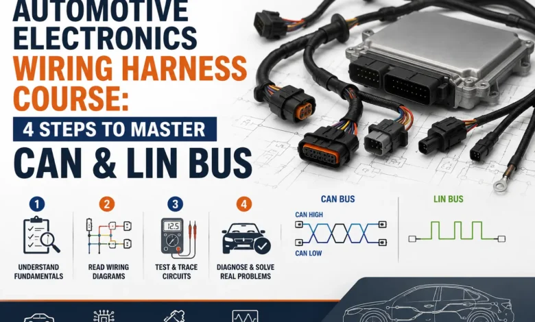
To keep modern vehicles efficient, engineers stopped running individual wires for every single component. Instead, they adopted a shared network architecture using two primary protocols: the Controller Area Network (CAN) and the Local Interconnect Network (LIN).
Think of the CAN Bus as a multi-lane high-speed interstate highway. It handles high-priority data between critical systems like the engine, transmission, and anti-lock brakes, allowing multiple modules to broadcast messages simultaneously. If you are serious about diagnosing a modern beater or building an embedded system project, understanding CAN topology is your entry ticket.
Conversely, the LIN Bus is like a quiet neighborhood street. It is a lower-cost, single-wire system designed for low-priority, non-critical accessories. You will find LIN bus connections operating your power mirrors, seat adjusters, and sunroofs, where ultra-high-speed data transmission simply isn’t necessary.
Inside CAN Frame Structure, Arbitration, and Bus Speeds
When studying a complete automotive electronics wiring harness course, learning to decode data packets is where the real magic happens. Modules communicate by sending structured packages of data known as “frames.”
Because multiple ECUs share the same wire, they use a process called “arbitration” to determine who gets to speak first. Messages are assigned specific priorities; for instance, a signal from the airbag sensor instantly overrides a command from the climate control system. This ensures zero latency when safety matters most.
Evolution of Speed: Classic CAN vs. CAN FD
Traditional CAN networks typically operate at speeds up to 1 Mbps, which served vehicles well for decades. However, the rise of advanced driver-assistance systems (ADAS) in newer vehicles has pushed data demands to the limit.
Enter CAN FD (Flexible Data-Rate). This updated protocol allows for significantly higher bandwidth and longer data payloads per frame. Understanding the functional differences between classic CAN, CAN FD, and LIN is essential for accurate diagnostics on any modern vehicle.
🎓 Direct Digital Access: Download Full Course Package
Get your copy of the Wiring Harness-CAN & LIN for Automotive Complete Course technical handbooks, message frame layouts, and practical schematics:
Network Troubleshooting Protocol: A Step-by-Step DIY Guide
When a network fault occurs, a vehicle’s communication can break down entirely. Follow this step-by-step diagnostic breakdown to pin down network faults without paying an expensive dealership premium.
- Hook Up Your Scan Tool: Connect an advanced OBD-II scanner to read network communication codes (typically “U-codes”). Note which modules are reporting “Lost Communication” to establish a map of the dead zone.
- Inspect the Gateway and Connectors: Visually audit the physical wiring harness. Look for loose pins, water corrosion in connector plugs, or harness sections that may have rubbed against sharp metallic brackets under the hood.
- Measure Bus Resistance: Turn off the vehicle’s ignition, disconnect the negative battery terminal, and use a digital multimeter to measure resistance across CAN High and CAN Low at the diagnostic link. A healthy network should read approximately 60 ohms due to its two parallel 120-ohm terminating resistors.
- Analyze with an Oscilloscope: For deep analysis, hook up a digital storage oscilloscope to view the actual voltage waveforms. Clean digital signals should show mirrored square waves toggling perfectly between designated voltage thresholds without noisy spikes.
The Ultimate Automotive Electronics Wiring Harness Course Specification Matrix
To help you visual how these networks match up against each other in real-world scenarios, review this comprehensive comparison matrix of vehicle communication protocols.
| Network Attribute | LIN Bus System | Classic CAN Bus | CAN FD System |
|---|---|---|---|
| Data Transfer Speed | Up to 20 kbps | Up to 1 Mbps | Up to 5+ Mbps |
| Physical Wire Count | Single Wire (Unshielded) | Twisted Wire Pair (Shielded) | Twisted Wire Pair (Shielded) |
| Primary Vehicle Role | Mirrors, Windows, Seats | Engine, Brakes, Transmission | ADAS, Radars, Camera Streams |
| Typical Cost Structure | Low-cost alternative | Standard industry baseline | Premium high-tier performance |
Whether you’re diagnostic planning for a customer’s Jeep Wrangler or diving into specialized engineering projects, referencing a verified automotive repair platform can provide the exact harness layouts and factory pinout specs needed to trace a problem down to the exact wire terminal.
Frequently Asked Questions (People Also Ask)
What are the symptoms of a failing automotive wiring harness?
Common signs of a compromised wiring harness include intermittent electrical issues, sudden diagnostic trouble codes (U-codes), random blown fuses, or modules that drop offline without warning. Physical indicators can also include wires showing brittle insulation, melted connector housings, or corrosion caused by water exposure near the primary junctions.
Can I diagnose a CAN Bus issue with a standard multimeter?
Yes, you can absolutely perform a preliminary diagnostic test using a digital multimeter. By checking the resistance across pins 6 and 14 on your OBD-II port with the vehicle battery disconnected, you can verify if the parallel circuit loop reads the correct 60-ohm standard. However, tracking down fast-acting electrical noise or intermittent signal dropouts requires an oscilloscope.
Why is understanding CAN FD important for modern automotive technicians?
CAN FD represents the next evolution of in-vehicle communications, enabling vehicles to transmit significantly larger payloads at much faster rates than standard networks. As modern platforms integrate increasingly complex features like lane assist, automated cruise control, and radar modules, being proficient with CAN FD protocols is an essential skill for any high-level automotive professional.